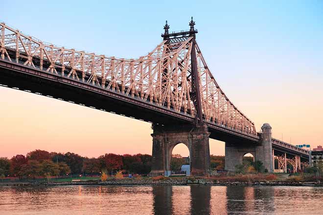
Bridges are such a common part of everyday life, they’re often taken for granted. Whether driving, walking, or traveling by train, they make it possible for us to cross bodies of water, valleys, roads, and other geological and manmade barriers. Equally important, they allow vital utility lines, including cables and pipelines, to span these barriers as well.
Let’s take a look at some common bridge designs, how they evolved over the centuries, and the purpose each design serves. While we’re at it, we’ll step back and admire a few notable examples of each. It could help you and your clients view bridges in a new light.
#1 – Beam bridge
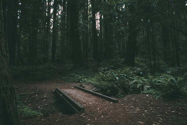
Beam bridges are generally considered the simplest form of bridge. How simple? When cavemen laid logs over streams to cross them, they were building the earliest beam bridges.
These basic bridges typically span relatively short distances. In order to build a beam bridge (also known as a girder bridge), all you need is a rigid horizontal structure (a beam) and two supports, one at each end, to rest it on. These things support the downward weight of the bridge and any traffic traveling over it.
The simplest beam bridge could be a log, wood plank, or stone slab laid across a narrow creek or stream. More complicated ones are usually constructed of steel or concrete or a combination of the two. The concrete elements may be reinforced, pre-stressed, or post-tensioned.

Structure of a typical beam bridge.
In supporting weight, a bream bridge endures both compressive and tension stress.
To understand how this works, think about this simple model or try it out in your garage. Imagine taking a board and laying it on top of two bricks. This is a simple beam bridge. If you were to place a heavy weight in the middle of the board, it would bend. The top side would bend in under the force of compression, and the bottom side would bend out under the force of tension. Add enough weight, and the “bridge” would eventually break. The top side would buckle and the bottom side would snap.
With this example, you can understand the factors an engineer needs to consider when designing a bridge.
Beam bridges are generally used to cross relatively short distances (usually less than 250 feet) because unlike other types of bridges, they have no built-in supports. The only supports are provided by piers. The farther apart the supports, the weaker a beam bridge gets. This doesn’t mean beam bridges can’t be used to cross longer distances, it simply requires that a series of beam bridges must be joined together, creating what’s known as a continuous span.
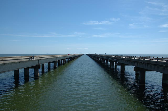
Lake Pontchartrain Causeway, Louisiana
- Carries: Four lanes of traffic
- Crosses: Lake Pontchartrain
- Location: Metairie and Mandeville, Louisiana
- Construction: Continuous-span beam bridge
- Length: 23.87 mi (38.442 km)
- Height: 15 ft
- Completed: 1956 (southbound), 1969 (northbound)
Longer, more complex beam bridges are built using many beams lined up side by side with a deck across the top of them. The main beams could be I-beams (also known as H-beams), trusses, or box girders. They could run halfway across the bridge or across its full length.
Beam bridges are used to carry pedestrians, automobiles, trucks, and rail lines across limited-distance spans. They’re frequently used for monorail and raised transit systems. They’re also valuable for carrying utility cables and pipelines over short distances to homes, isolated communities, and subdivisions.
Hint: Many beam bridges are historic structures, and there are limits as to how utilities can be conveyed over them. The state of Connecticut, home to many such historic bridges, offers guidelines on how to handle this.
#2 – Truss bridge
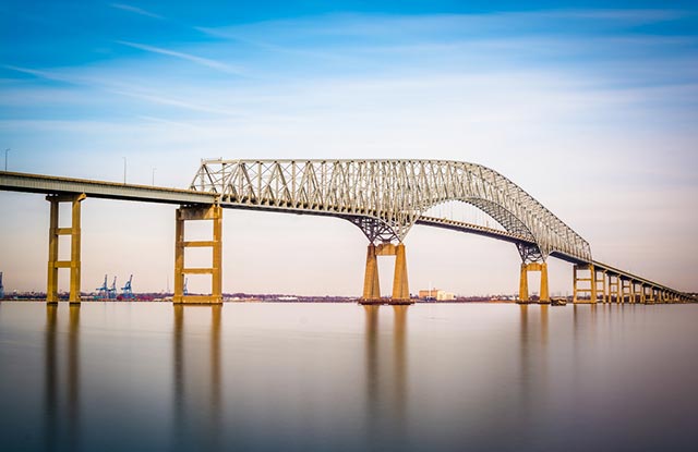
Francis Scott Key Bridge – Baltimore, Maryland
- Carries: Four lanes of traffic
- Crosses: Patapsco River
- Location: Baltimore, Maryland
- Construction: Steel arch-shaped continuous through truss bridge
- Length: 8,636 feet
- Height: 185 feet
- Completed: 1977
A truss bridge features a prominent truss, which is a structure of connected elements that form triangular units. A truss is used because it’s a very rigid structure that transfers the load from a single point on a bridge to a much wider area. Truss bridges can cross longer spans than basic beam bridges.
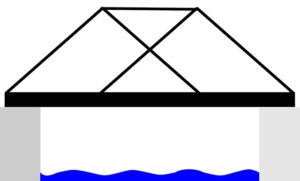
Structure of a typical truss bridge.
Truss bridges appeared very early in the history of modern bridges. They’re relatively economical to build because they use materials efficiently.
Truss bridges were built mostly of wood in the early 1800s and slowly shifted to iron construction by the middle of that century. Steel became the standard by the 1880s. Some states continued building steel truss bridges through the 1930s, while others abandoned them sooner, choosing to build concrete girder and beam bridges instead.
Examples of these bridges still exist across the United States, but the number is decreasing because they’re being demolished and replaced with more modern types of bridges. Some truss bridges are extremely plain and utilitarian, while others use more elaborate design details.
Throughout history, engineers experimented with different forms of truss bridges, trying to find better ways to solve particular problems. A truss bridge can have a deck or roadbed on top (deck truss), in the middle (through truss), or at the bottom of the truss. If the sides of the truss extend above the roadbed but are not connected, it is called a pony truss or half-through truss.
Truss bridges are crossed by pedestrians, automobiles, trucks, light rail, and heavy rail. They’re usually used to span rivers rather than roads. Truss bridges have historically been used to carry water and sewage through pipes across spans. Over the years, electrical and cable lines were added as well. Much of this utility infrastructure is aging, and even if the bridge isn’t being replaced, utility lines often need to be.
Note: It’s important to use safe equipment designed specifically for under-bridge maintenance when updating aging utility infrastructure under truss bridges. Check out these examples.
#3 – Cantilever bridge
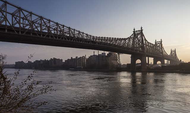
Ed Koch Queensboro bridge – New York City
- Carries: Ten lanes of traffic, four upper, six lower, plus lanes for pedestrians & bicyclists
- Crosses: East River
- Location: New York City (Manhattan to Queens)
- Construction: Double-decked cantilever bridge
- Length: 3,724 feet
- Height: 130 feet
- Completed: 1909
These types of bridges are built using cantilevers, which are structures that project horizontally into space, supported on only one end. For small footbridges, the cantilevers may be simple beams. Larger cantilever bridges designed to handle road or rail traffic use trusses built from structural steel or box girders built from pre-stressed concrete.
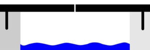
Structure of a cantilever bridge.
Steel truss cantilever bridges were a major engineering breakthrough in the 1800s, since they can span distances of over 1,500 feet and are more easily constructed at difficult crossings, such as highways, deep waterways, or populated areas, using little or no ground support.
Engineers build longer cantilever bridges by adding more supports. This distributes the load among them, which helps achieve greater length.
Cantilever bridges can be built without false-work below and supporting towers and cables above. This level of construction simplicity is one of their great advantages. They’re also of very rigid construction, so they can carry relatively large loads, including rail lines, which is a common use for these bridges.
Many of these bridges carry utilities across their spans in dense urban areas. Check out this example of a major project that coordinated installation of a variety of utilities, including fiber-optic networks, gas, water, extensive stormwater, wastewater, and government-secure communication lines in a single project.
#4 – Arch bridge

Stone Arch Bridge – Minneapolis, Minnesota
- Carries: Pedestrians and bicyclists
- Crosses: Mississippi River
- Location: Minneapolis, Minnesota
- Construction: 21 stone arch spans and one steel deck truss span
- Length: 2,100 feet
- Width: 28 feet
- Completed: 1883
The arch bridge is one of the most common types of bridges. They came into use over 3,000 years ago and remained popular until the industrial revolution. At that time, the invention of steel, concrete, and other advanced materials helped engineers develop other modern bridge designs. However, arch bridges remain in use even today, and with the help of modern materials, they can be built larger than they were in the past.
An arch bridge has abutments at each end and is shaped as a curved or pointed arch. Arch bridge engineering is based on transferring the weight of the bridge and its loads partially into a horizontal thrust pushed back together by the abutments at either side of the bridge. A longer bridge can be made from a series of arch bridges, although more economical options are typically used today.

Structure of a simple arch bridge.
Did you know? It is the arch itself that gives its namesake bridge its strength. In fact, an arch made of stone doesn’t require mortar.
Believe it or not, stone and wood arch bridges became very popular during the Roman Empire. Roman engineers built over 1,000 stone arch bridges in Europe, Asia, and North Africa. Many of those bridges remain standing even today, demonstrating their strength and durability. Similar bridge-like structures were among the first to serve a utility-related function. They were used to carry water from outside of cities into urban areas, similar to how bridges today carry pipes to transport water from place to place.
As centuries went on, medieval architects improved on earlier designs, creating arch bridges with narrower piers, thinner arch barrels, pointed arches, and increased arch spans. Renaissance architects not only built some of the most structurally sound bridges in history, they also created some of the most beautiful. The Rialto Bridge in Venice is one such example. In the last 150 years, bigger and more ambitious arch bridges have been built out of iron, steel, and concrete.
The strength and durability of arch bridges allow them to be used to carry pedestrians, vehicles, light rail, and heavy rail, and as mentioned, some have been built to exclusively carry water from place to place. When it comes to supporting modern utilities, arch bridges are often not effective. It’s impossible to support the required infrastructure within the arch, and placing it along the side of a bridge can be unsightly and leave them exposed to weather.
In fact, most states offer guidance on how utilities should be suspended from bridges, and it’s hard to find any that offers advice on how to do so on an arch bridge, except for this example from the state of Washington.
#5 – Suspension bridge

Golden Gate Bridge – San Francisco, California
- Carries: Six lanes of traffic, pedestrians and bicyclists
- Connects: San Francisco and Marin County, California
- Construction: Suspension, truss arch, and truss causeways
- Length: 8,981 feet
- Height: 746 feet
- Completed: 1933
This type of bridge has suspension cables between towers and suspender cables hanging from towers, which hold the deck. Suspension cables are anchored at each end of the bridge, and they carry the majority of the load.
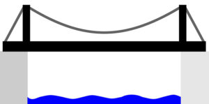
Structure of a suspension bridge.
Today’s complex suspension bridges evolved from simple versions dating back to the fifteenth century. They had load-bearing cables but no towers. The most basic suspension bridges include rope, net, and other woven bridges.
The first modern-style suspension bridge in the United States was built in Pennsylvania in 1801. Over the years, suspension bridges became popular because they spanned wide gaps that other bridges could not. In addition to this, they’re less expensive to build because they use less material than most other bridges.
Suspension bridges are more earthquake-proof than virtually any other bridge type. In addition, it’s easy to update them to make room for wider vehicles or additional traffic lanes. It’s also relatively easy to suspend utility cables and power lines over long distances on a suspension bridge.
The negatives: the construction tends to be very rigid in order to make them stand up to high winds, and most cannot handle the heavy weight of trains. It often takes special hangers to support utility infrastructure off complex types of suspension bridges.
#6 – Tied-arch bridge
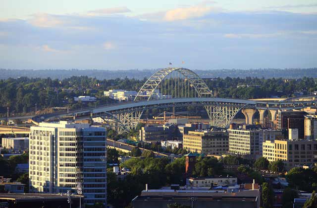
Fremont Bridge – Portland, Oregon
- Carries: Four lanes, two decks of traffic
- Crosses: Willamette River and streets
- Location: Portland, Oregon
- Construction: Tied-arch bridge
- Length: 2,154 feet
- Height: 381 feet
- Completed: 1973
A tied-arch bridge (also called bowstring-arch or bowstring-girder bridge) is a type of bridge that has an arch rib on each side of the roadway (deck) and one tie beam on each of the arches that support the deck. Vertical ties connected to the arches support the deck from above.
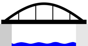
Structure of a tied-arch bridge.
This type of bridge can be thought of as a cross between an arch and a suspension bridge. The combined construction style allows the bridge to be built with less bulky foundations than arch bridges, which means they’re a great option for difficult locations that require elevated piers or in places where the soil is unstable. The arch construction makes them ideal for situations when a bridge needs to be built offsite, delivered, and slid into place onsite. This is not possible with suspension bridges.
Tied-arch bridges may have many benefits, but they’re not perfect. They require welds at the connection between the arch rib and the tie girders and at the connection between the arch and vertical ties. These welds have to be repaired regularly, which can be costly, time consuming, and inconvenient. Construction and design of this type of bridge is non-redundant, which means that if even one of the two tie girders fail, the whole structure will collapse. Finally, tied arch bridges are more expensive to build compared to the other types of bridges of the same length.
The simple construction of this type of bridge makes them good for supporting utility pipes and cables.
#7 – Cable-stayed bridge
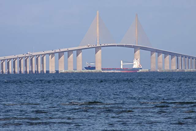
Bob Graham Sunshine Skyway Bridge – Tampa Bay, Florida
- Carries: Four traffic lanes
- Crosses: Tampa Bay, Florida
- Construction: Continuous prestressed concrete cable-stayed bridge
- Length: 1.1 miles
- Height: 430 feet
- Completed: 1987
At first glance, a cable-stayed bridge may look like a variation of a suspension bridge, but they are structurally different. Unlike suspension bridges, cable-stayed bridges don’t require anchorages and two towers aren’t necessary. Instead, the cables can run from the roadway up to a tower that holds all the weight.
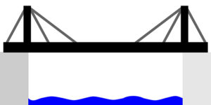
Structure of a cable-stayed bridge.
The basic design of the cable-stayed bridge goes back almost 500 years. Modern versions started being built in Europe after World War II as cost-effective replacements for bridges damaged during the war.
The tower of a cable-stayed bridge absorbs and distributes all the compressional forces of the bridge. The cables can attach to the roadway in different patterns. For example, in a radial pattern, cables extend from several points on the road to a single point at the tower. In a parallel pattern, the cables attach to both the roadway and the tower at several separate points.
Today, cable-stayed bridges are a popular choice as they offer all the advantages of a suspension bridge but at a lesser cost for shorter spans. They require less steel cable, are faster to build, and incorporate more precast concrete sections. Designs for some of these bridges can offer a significant wow-factor.
Conclusion
Each type of bridge serves a different purpose and can be used to span different types of gaps and barriers. However, bridges are more than just utilitarian objects. They’re also engineering marvels and things of beauty. We hope this overview helps you further appreciate the details of the bridges you cross each and every day.
For even more bridge appreciation, check out our post on the Greatest American Bridges.
